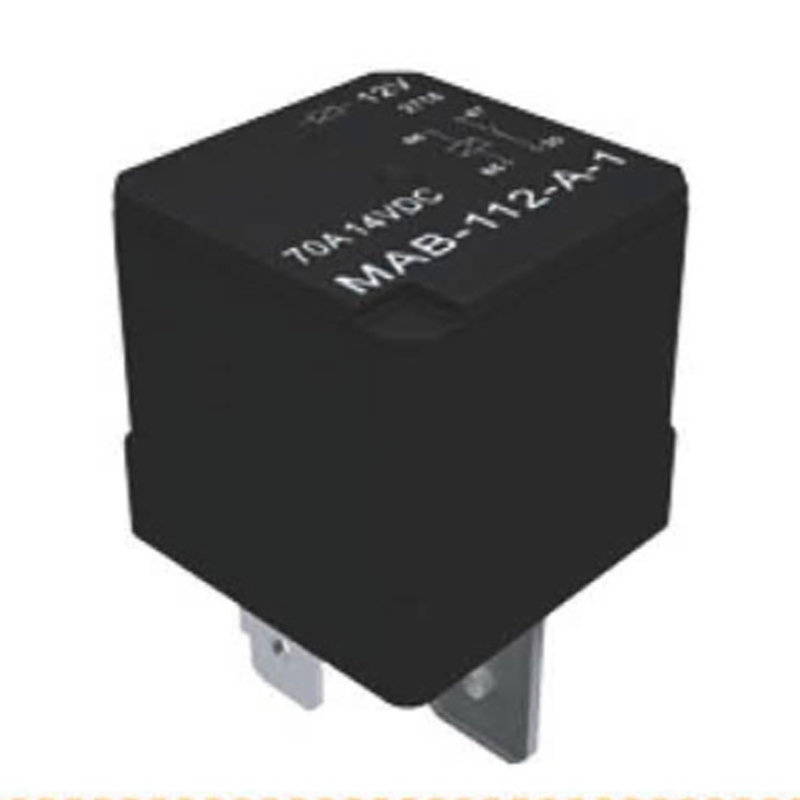
| MAB | S | 1 | 12 | A | 1 | Y | R |
| Product number | Product structure | Number of contact groups | Coil voltage | Contact form | Structural form | Pin form | Coil parallel element |
| S: plastic type None: dust cover type | 1: 1 group | 06: 6VDC 12: 12VDC 24: 24VDC | A: NO | 1: optical back fast connection terminal 2: PCB terminal 3: iron back fast connection terminal 4: plastic back fast connection terminal | None: QC pin with lock hole Y: QC pin without lock hole | None: Without transient suppression resistor R: shunt resistor D1: shunt diode(anode connection #86) D2: shunt diode(anode connection #85) |
| Contact parameters | Performance parameters |
| Contact form | 1A | Insulation resistance | 100MΩ (500VDC) |
| Contact material | Silver alloy | Medium pressure | Between contact and coils: 500VAC 1min Between open contacts: 500VAC 1min |
| Contact drop (initial) | Typical 20mV, Maximum 300mV | Action time | ≤10ms |
| Maximum continuous current | 70A (23℃), 50A (125℃) | Release time | ≤10ms |
| Maximum switching voltage | 50VDC | Ambient temperature | -40℃~+125℃ |
| Electrical life | 100000 | Vibration | 10Hz~500Hz 49m/s2 |
| Mechanical life | 1000000 | Impact | 294m/s2 (30G) |
| Terminal way | Quick connect type terminal |
| Package type | Plastic package type, dust cover type |
| Weight | About: 35g |
| Mechanical behavior | Shell retention: (pull and compression)200N Pin holding force: (pull and compression)100N Pinout resistance to bending force: (all direction) 10N |
Coil Spec Sheet
| Rated voltage VDC | Operating voltage VDC | Release voltage VDC | Coil resistance Ω±10% | Coil power W | Parallel resistance Ω±10% | Equivalent resistance Ω±10% | Maximum allowable coil voltage VDC |
| 20℃ | 85℃ |
| 6 | ≤4.2 | ≥0.6 | 22.5 | 1.6 | - | - | 10.1 | 7.8 |
| 6 | ≤4.2 | ≥0.6 | 22.5 | 1.8 | 180 | 20 | 10.1 | 7.8 |
| 12 | ≤8.4 | ≥1.2 | 90 | 1.6 | - | - | 20.2 | 15.7 |
| 12 | ≤8.4 | ≥1.2 | 90 | 1.8 | 680 | 79.5 | 20.2 | 15.7 |
| 24 | ≤16.8 | ≥2.4 | 360 | 1.6 | - | - | 40.5 | 31.5 |
| 24 | ≤16.8 | ≥2.4 | 360 | 1.8 | 2700 | 317.6 | 40.5 | 31.5 |
Note: When the contact has no load current and the coil resistance is the minimum value, the maximum continuous working voltage allowed to be applied to the relay coil.
Load parameters
| Load voltage | Load type | Contact load current A | On-off s | Electrical durability (times) | Test ambient temperature |
| On | Off |
| 14VDC | Resistive | on | 2 | 2 | 100000 | At 23℃ |
| off |
| Perceptual | on | 2 | 4 | For details, please refer to the environmental temperature curve of the electrical durability test. |
| off |
| Lamp | on | 0.5 | 10 |
| off |
| 27VDC | Resistive | on | 2 | 2 | At 23℃ |
| off |
Previous: YUANKY timer 16A SPDT DPDT din rail 2 LED status indicators staircase light time switch Next: YUANKY household UK standard surge protector spikes 480J 4.5kA 230V 4 way 13A extension board extension socket with usb

