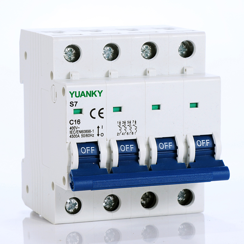
|
America
General rules for choosing MCB.
Technical data of the network at the point considered:
The earthing systems, short-circuit current at the circuit breaker installation point. which must always be less than the breaking capacity of this device, network normal voltage.
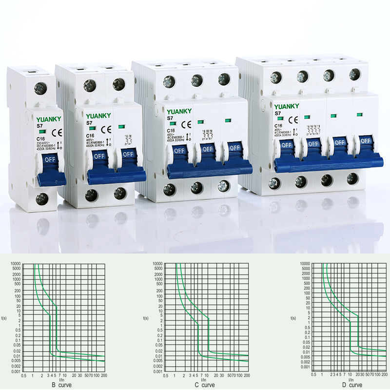
There are 3 curve characteristics for magnetic operation:
B curve (3-5In) protection and control of the circuits against length cables in TN and IT SYSTEMS.
C curve (5-10In) protection and control of the circuits against overloads and short-circuits; protection for resistive and inductive loads with low inrush current.
D curve (10-20In) protection and control of the circuits against overloads short-circuits; protection for circuits which supply loads with high inrush current at the circuit closing (LV/LV transformers, breakdown lamps).
Specifications
Each pole of the circuit breaker power consumption
| ElectricalFeatures | Standard | IEC/EN 60898-1 | |
| Rated current In | A |
1,2,4,6,10,16,20,25,32,40,50,63 | |
| Poles | P |
1,2,3,4 | |
| Rated voltage Ue | V |
AC 240/415 | |
| Insulation voltage Ui | V |
500 | |
| Rated frequency | Hz |
50/60 | |
| Rated breaking capacity | A |
3000,4500(2~40A/6000) | |
| Rated impulse with stand voltage(1.2/50) Uimp | V |
4000 | |
| Dielectric test voltage at ind. Frqu, for 1 min | KV |
2 | |
| Pollution degree | 2 | ||
| Thermo-magnetic release characteristic | B,C,D | ||
| Electrical life | T |
4000 | |
| Mechanical life | T |
10000 | |
| Protection degree | IP20 | ||
| Reference temperature for | ℃ |
30 | |
| Setting of thermal element | |||
| Ambient temperature(with daily average ≤35℃) | ℃ |
-5~+40(Special application please refer to temperature compensation correction) | |
| Storage temperature | ℃ |
-25~+70 | |
| Installation | Terminal connection type | Cable/Pin type busbar/U type busbar | |
| Terminal size top/bottom for cable | mm2 |
25 | |
AWG |
18-3 | ||
| Terminal size top/bottom for busbar | mm2 |
25 | |
AWG |
18-3 | ||
N*m |
2 | ||
In-Ibs. |
18 | ||
| Mounting | |||
| Connection |
Temperature derating
Please refer to table below for temperature compensation correction
| RatedCurrent In(A) | Temperature compensation coefficient under various operating temperature | ||||||||
-10℃ |
0℃ |
10℃ |
20℃ |
30℃ |
40℃ |
50℃ |
55℃ |
60℃ |
|
| 1-6 | 1.20 |
1.14 |
1.09 |
1.05 |
1.00 |
0.96 |
0.80 |
0.75 |
0.70 |
| 10-32 | 1.18 |
1.12 |
1.08 |
1.04 |
1.00 |
0.96 |
0.92 |
0.88 |
0.84 |
| 40-60 | 1.16 |
1.12 |
1.07 |
1.03 |
1.00 |
0.97 |
0.87 |
0.83 |
0.80 |