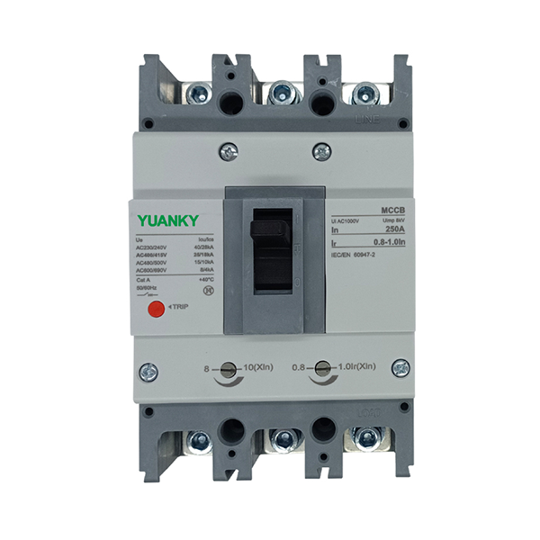
Product Features
This breaker’s rated in sulation volage is 690V, is applied to distribution network circuit of AC 50HZ, rated working voltage up to 690V, rated working current up to 800A, which is for electricenergy distribution, circuit protection, protecting power supply facility from destroying by the foult of overloading, short circuit and undervoltage ,meanwhile it is also used for protection from unfrequent starting, over loading, short circuit and unervdtage of the eletromotor.
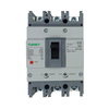
This breaker has such characteristics of company volume, high short circuit interrupting capacty, shortflach arcing and etc which is a ideal product for users,This breaker can be installed vertically(upright),and also horizontally.
This breaker comply with standard IEC60947-2、GB 14048.2.
Miniaturization design
Product volume miniatu rization, such as the size of the same size of the original 125 shell shelf 63 sheu, can meet the customer’s personality needs of the product installation size
Size uniform
The same shell level, different sub ability(C、S、M、H)、different functions (air,leakage )product installation size is completely consistent
The function of the reasonable parameter setting
Circuit breaker can realize long-time delay overload inwerse time, short circuit instantaneous action protection functions such as paramets setting, users can set their own protective properties required,the distribution network is used in the circuit breaker on the lower levet with more reasonable.
Suitable working environment and installation condition
Altitude less than 2000m
Ambient medium temperature is from -50 Cto+40C(+45C for shipping product)
Can withstand moist cuir
Can with stand mold
Can withstand nuclear radiation
Max incination is 22.5°
It can still work reliably if the product subjects to the normal vibration from ships
It can still work reliably if the product subjects to the earthquake(4g)
Put in the place where is no explosion danger and conductive dust, cant corrode metel and destroy the insnlation sleet.
Put in the place where is no sleet.
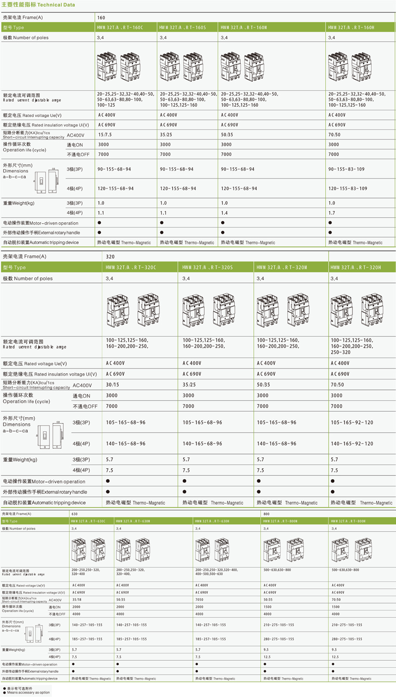
Selection Guide
HWM32 RT - 160 H Z / 3 300 2 A Q1 D Q 2
| Type | The adjustable type | Frame Inm | Breaking capacity Icu/Ics(KA) |
| HWM32 | RT | 160 | H |
| MCCB | RT: Therm-magT/A:Therm/mag | 160,320,630,800Remark:160 Frame upgrade from 125320 Frame upgrade from 250630 Frame upgrade from 400 | 160320630800 | C15/7.530/1535/18 | S35/2535/25 | M50/3550/3550/3550/35 | H70/5070/5070/5070/50 |
| Operation | Poles | Tripping mode and inner accessary | Rated current(A) |
| P | 4 | 300 | 160 |
| P:Motor-drivenZ:Rotory handleW:DirectMotor-driven operationDC1, DC2, DC3 | 2:2P3:3P4:4P | First figure means tripping unit way2:Only with magnetic release3:Thermal release+magnetic release bodyRemark:The last two figures means accessory code
(see accessaries list) | 160320
630 800 | 20-25, 25-32, 32-40, 40-50,50-63, 63-80, 80-100,100-125, 125-160100-125, 125-160,160-200, 200-250,
250-320 200-250, 250-320, 320-400, 400-500, 500-630 500-630, 630-800 |
| Application | Option for 4P MCCB |
| 2 | A |
| 1:Power distribution2:Motor-protection | A:N pole without protection, ON/OFF withoutB:N pole without protection, ON/OFF switched |
| Accessary Voltage | Motor-driven operation voltage | Connection | Connection plate |
| Q1 | D1 | Q | 2 |
| UVTQ1:AC220VQ2:AC240VQ3:AC380VQ4:AC415V | ShuntF1:AC220VF2:AC380VF3:DC110VF4:DC24V | AuxiliaryJ1:AC125VJ2:AC250VJ3:DC125VJ4:DC24V | DC1D1:AC220VD2:AC230VD3:AC380VD4:AC400V | DC3D5:AC230VD6:AC110VD7:DC220D8:DC110
D9:AC110-240V D10:DC100-220V | Q:FrontH:RearC:Plug-in | 1:W/O2:W |
| Remark: DC1, DC3 motor-driven operating voltage see extenal accessaries table. |