Suitable range
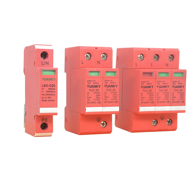
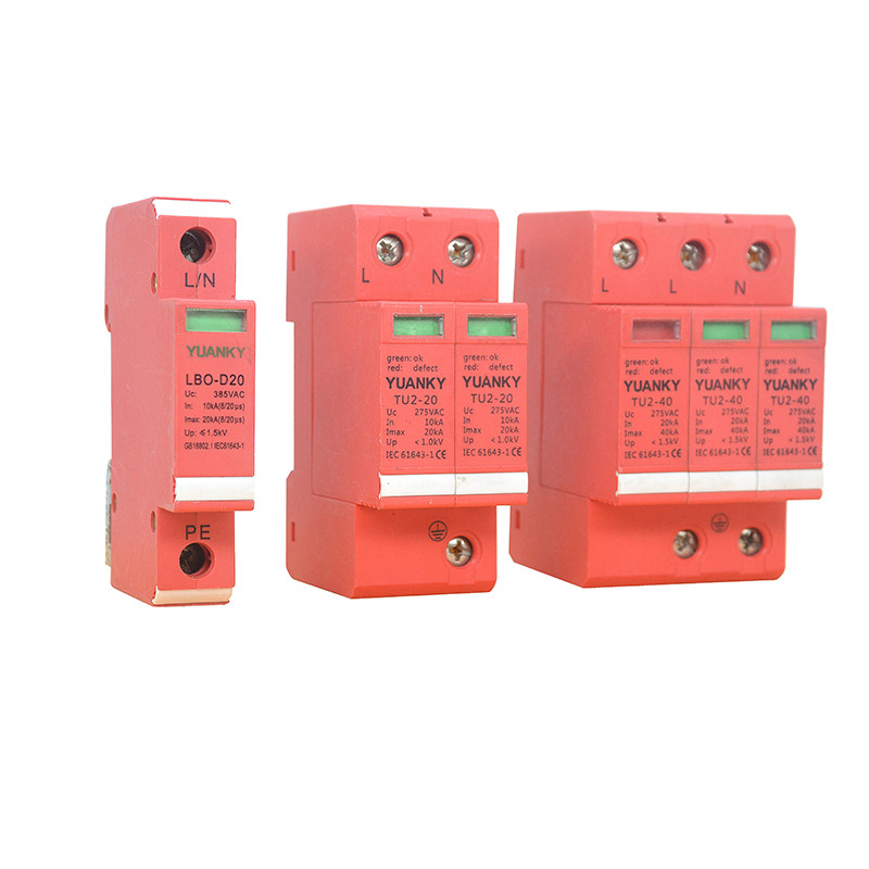
TU2 SPD is generally parallel connected onto the front circuit of the required protected circuit equipment, as close as possible the down circuit terminal. The SPDis connected with one end of the circuit conductor(phase line L or neutral line N), and the other end of the connecting line of equipment grounding device, for the lightning equipotential connection.
Model | Protection zone | Protection level | Suitable location |
TU2-10
TU2-20 | LPZ1,LPZ2 zone boundaries of and LPZn
zone | Class 3 | Normally installed in the distribution box of the premises; or installed in the computer information equipment, electronic equipment and control equipment, or the nearest lighting box, socket box. |
TU2-40
TU2-60 | boundaries of LPZ0B and LPZ1 zone,or LPZ1 and LPZ2 zone | Class2 | Usually installed in the building distribution electric box,metering box;or installed in the computer center,motor housing,building control room,monitoring room, industrial automation,operation room and other places of power distribution box;also can be installed in the general distributionbox of the six floors below building, or the general distribution box of villa |
TU2-80
TU2-100 | LPZOA,LPZ0B zone boundaries of LPZ1 zone | Class1 | Usually installed in the piercing
lined low voltage main distribution
cabinet |
TU2-1 | Used in LPZ0A,LPZ0B zone | Class 1 | Usually used in lightning riskhigher equipment system of the first primary surge protection, installed in the general distribution box of distribution box, outdoor distribution box and so on. |
Distribution network grounding systemvoltage
Grounding system | TT system | TN-S system | TN-C-Ssystem | IT system |
The maximum voltage of the grid | 345V/360V | 253V/264V | 253V/264V | 398V/415V |
Main technical parameters and performance
Project Name | Parameter | TU2-10 | TU2-20 |
Nominal discharge current | In(kA) | 5 | 10 |
Maximum discharge current | Imax(KA) | 10 | 20 |
Maximum continuous operating voltage | Uc(V) | 275 | 320 | 385 | 275 | 320 | 385 |
Voltage protection level | Up(kV) | 1.0 | 1.3 | 1.3 | 1.3 | 1.5 | 1.5 |
Test classification |
| Grade III testing | Grade III testing |
Poles |
| 2,4,1N | 2,4,1N |
Structure type |
| D,B type | D,B type |
operation status | Window indicator | Colorless or green:normal,red: fault | Colorless or green:normal,red: fault |
Backup protective
appliances(suggestion) | Backup fuse | gl/gG16A | gl/gG16A |
Backup CB | C10 | C16 |
dimensions |
| Refer to drawing no.1,3,4 | Refer to drawing no.1,3,4 |
Project Name | Parameter | TU2-10 | TU2-20 |
Nominal discharge current | In(kA) | 20 | 30 |
Maximum discharge current | Imax(KA) | 40 | 60 |
Maximum continuous operating voltage | Uc(V) | 275 | 320 | 385 | 420 | 275 | 320 | 385 | 420 |
Voltage protection level | Up(kV) | 1.5 | 1.5 | 1.8 | 2.0 | 1.8 | 2.0 | 2.2 | 2.2 |
Test classification |
| Grade III testing | Grade III testing |
Poles |
| 1,2,3,4,1N,3N | 1,2,3,4,1N,3N |
Structure type |
| D,B,X type | D,B,X type |
operation status | Window indicator | Colorless or green:normal,red: fault | Colorless or green:normal,red: fault |
Backup protective
appliances(suggestion) | Backup fuse | gl/gG40A | gl/gG60A |
Backup CB | C32 | C50 |
dimensions |
| Refer to drawing no.1,3,4 | Refer to drawing no.1,3,4 |

